Cleancab Installation Instructions
1.PURPOSE
The purpose of this document is to provide general guidance and information on the installation of the Cleancab filtration system provided.
2.PRESSURISER INSTALLATION
NOTE: The steps below are basic generic steps on the installation of a pressuriser system. Onsite teams will have to complete a detailed risk assessment and work instructions on the specific machine and system to be installed.
Isolate machine.
Locate an appropriate location to mount the pressuriser unit. Note the pressurisercan be fitted horizontal or vertical with the use of a different per-filter cover.Contact Cleancab if you require the vertical cover. Horizontal cover is supplied asa standard part. See photo 1A horizontal mount 1B vertical mount. Note theVacuator valve must always face down go to page 6 for powercore recommendedmounting positions
Remove filter cover using procedure laid out in Hepa filter replacement guide page 4
Remove filter certificate & warning sticker (located inside the box on top of the Hepa filter)
Fit warning stickers to prominent location inside the operator station. PlaceCertificate in a safe place for commissioning of the system.
Drill holes through the base of the pressuriser housing & mount securely with 4bolts. Orientate the outlet duct to the desired position. The outlet duct can beplaced in any direction & if required drill a 76mm hole in the base of thepressuriser so the duct can be placed out the base of the unit. See pictures ofoptions. NOTE. seal duct & blanking plates with sealant when being refitted.
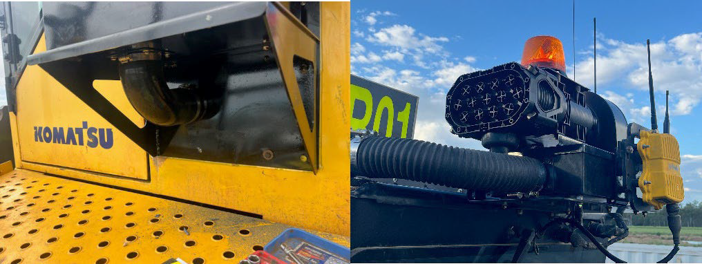
Ducting out the base of the unit. 1A: Horizontal mount side duct placement
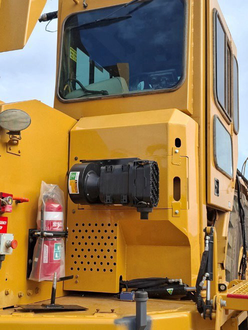
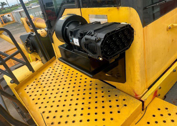
Ducting out the base of the unit. 1A: Horizontal mount side duct placement
1B: Vertical mount base ducted 1A: Horizontal mount base ducted placement
7. Reassemble pressuriser.
8. Locate cabin fresh air filter & remove factory filter.
9. Manufacture an adapter or contact Cleancab for a range of adapters available.
10. Remove or disconnect fresh air/recirculation flap if fitted.
11. Inspect AC system evaporator box for damage or poor seals. Repair as required.
12. Clean evaporator core if required following safety procedures.
13. Fit adapter to fresh air inlet cover.
NOTE: Depending on machine make/model an adapter may be supplied.
If no adapter is supplied manufacture an adapter with a 75mm outlet.
NOTE: best practice is to always duct the pressurised air into the AC plenum chamber through the fresh air intake to allow mixing with therecirculated air.
14. Connect pressuriser to fresh air adapter with 76mm ducting.
15. Fit cabin pressure monitor & sensor box in a safe appropriate location in the cabin.Follow Cleancab installation guidelines supplied with the Pressuriser & monitor orvisit Cleancab website for more information
16. Follow instructions for system setup in the Cleancab installation & maintenancemanuals. All Cleancab manuals are on the website in the operator’s section.
17. Run pressuriser with factory HVAC system off to test
18. Test for system operating pressure the cabin pressure must be above 20PA, recommended 35-50Pa. Cleancab target pressure is set to 35PA from factory. If this pressure cannot be achieved carry-out smoke test for cab sealing. (Note. The Cleancab pressuriser can achieve 60PA @ 100% fan speed with a 40mm Diameter hole in the cabin)
19. A good, sealed cabin should achieve 35PA with a fan speed of less than 70% minimum of 20%. See operating manual for more information on Fan speed verses cabin pressure.
20. Note. The Cleancab system has automatic pressure control & will start & hold 100% fan speed for 30 seconds after which it will decrease the fan speed until the target pressure is reached.
21. Test air conditioning system for performance & repair as necessary.
NOTE: The cabin pressuriser system adds more load to the air conditioning system. It is best practice to seal the cabin as best as possible to reduce the heat load on the air conditioning system.
22. Update filter service records using the Cleancab APP
23. Complete system commissioning form using the Cleancab App report or the form available on the Cleancab website. Keep a copy of the commissioning form & the Hepa filter certificate with machine records,
24. It is recommended to complete CO2 gain test. A information sheet on CO2 gain has been included with the pressuriser.
Cleancab Hepa Filter Replacement
1.Remove main filter pre-cleaner & wiring from filter motor.
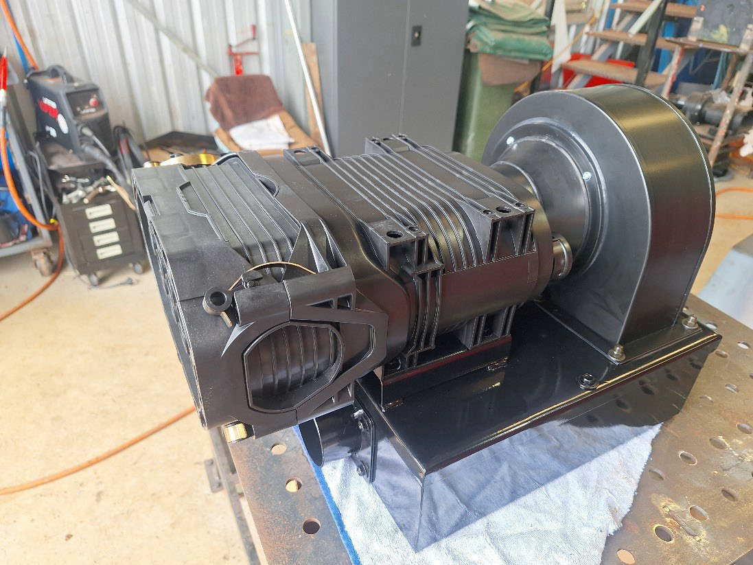
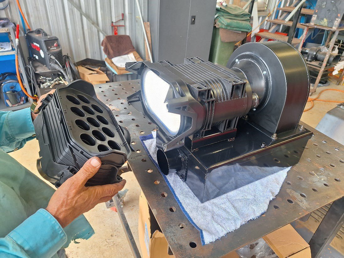
2.Remove 4 x 10mm nuts from filter base.
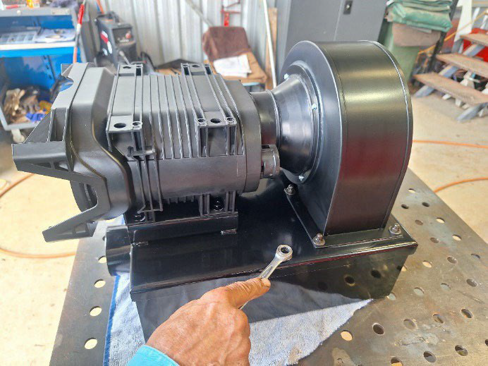
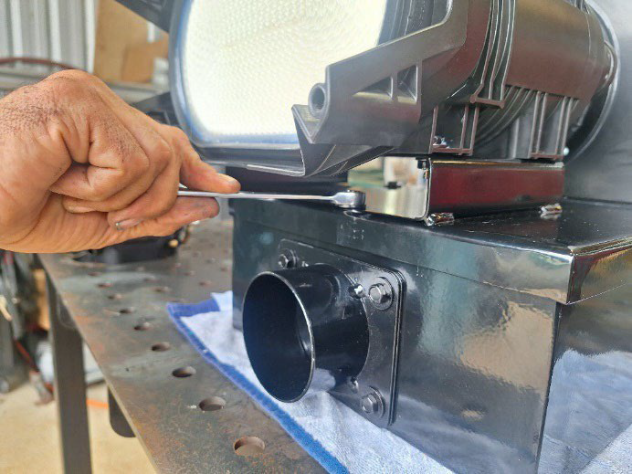
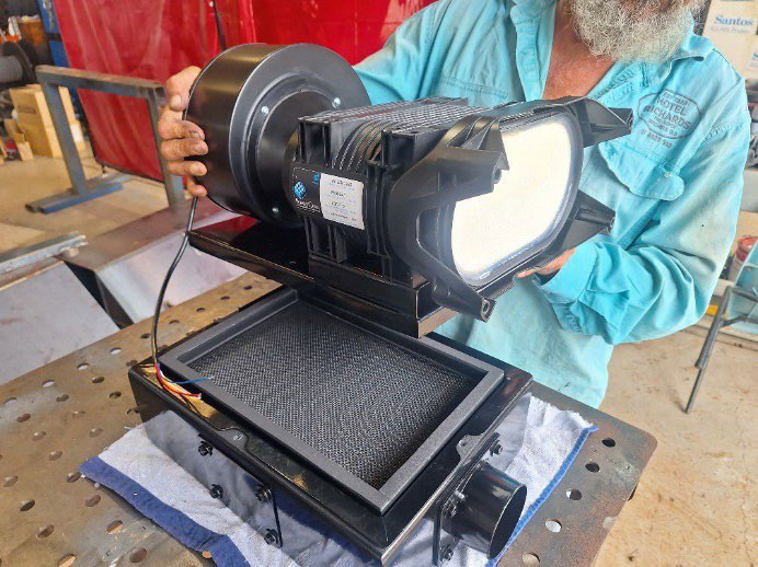
Remove filter cover assembly
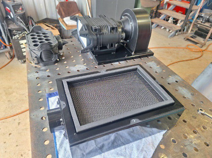
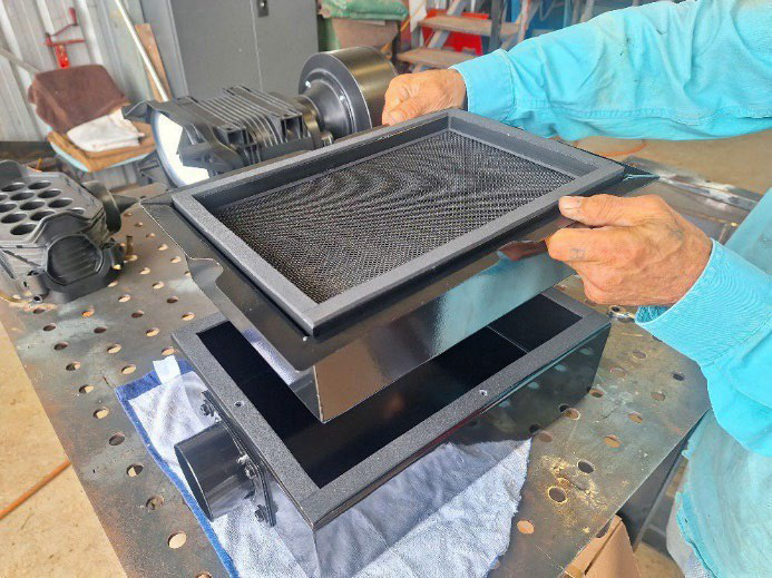
Refit all components & test run system for system pressurisation
10mm nuts to be tensioned to 2nm in a diagonal direction starting at the sidefirst. Repeat procedure to final tension of 4nm.
Powercore filter mounting positions
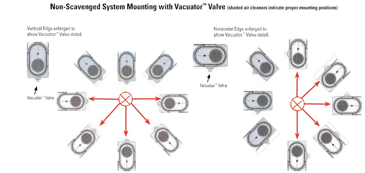
Powercore filter mounting positions