CLEANCAB FILTRATION SYSTEMS wiring diagram & test information sheet.
CLEANCAB FILTRATION SYSTEMS wiring diagram & test information sheet.
Notes
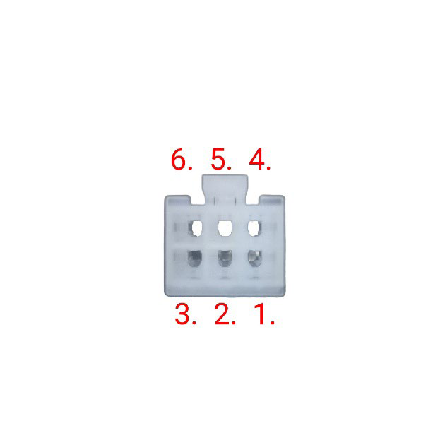
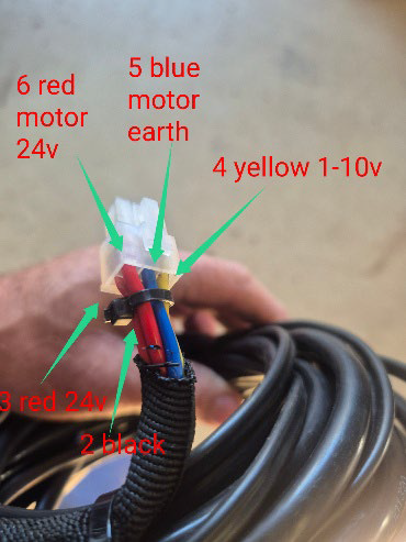
Molex main connector: Molex 39012060 (6-pin). Pin 1 not used.
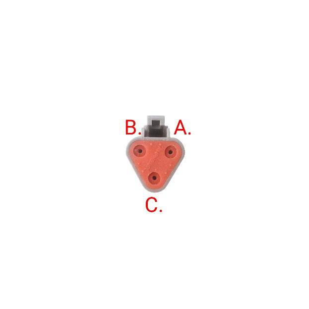
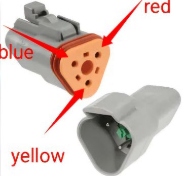
Deutsch fan connector: DT06-3S (3-pin). Cavity letters A/B/C as specified.
Two harnesses:
o3-core (red/blue/yellow) between Molex and Deutsch
o2-core (red/black) between Molex and 24 V battery.
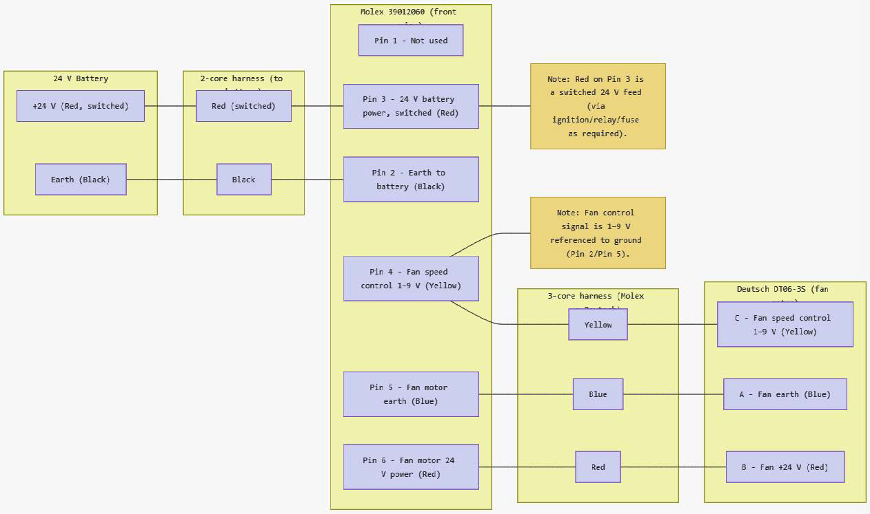
Wiring summary:
Molex 39012060
Pin 1: Not used
Pin 2: Earth to battery — black — to battery negative
Pin 3: 24 V battery power (switched) — red — to battery positive viaignition/relay/fuse
Pin 4: Fan speed control 1–9 V — yellow — to Deutsch C
Pin 5: Fan motor earth — blue — to Deutsch A
Pin 6: Fan motor 24 V power — red — to Deutsch B
Deutsch DT06-3S (fan motor)
A: Blue — fan earth — from Molex Pin 5
B: Red — fan +24 V — from Molex Pin 6
C: Yellow — fan speed control 1–9 V — from Molex Pin 4
Harnesses
2-core: Black from Molex Pin 2 to battery negative; Red from Molex Pin 3 toswitched +24 V.
3-core: Red from Molex Pin 6 to Deutsch B; Blue from Molex Pin 5 toDeutsch A; Yellow from Molex Pin 4 to Deutsch C.
Implementation tips:
Put a fuse on the switched +24 V feed to Pin 3 sized for the fan current plusheadroom.
Keep the control line (yellow) away from high-current runs to minimize noise; shieldif needed.
Confirm Deutsch cavity orientation from the connector keying before crimping.
Note to test full system leave fan motor connected system powered on & probe fromfan side of the DT06-3S connector.
Note fan motor will not run if supply power is below 17V or above 30V
Fan speed control 9V=100% 1V=9%
DT06-3S pin out Molex 39012060 pin out